Introduction
Hello and welcome !
Very short introduction:
A tachymeter is a
theodolite with a built-in capability to measure distances.
And a theodolite measures angles accurately.
Since tachymeters do angles and distances, they are also called "total
stations".
Every building site, from garage to skyscraper, uses tachymeters to define and verify the position, size and shape of a building.
Today, Satellite navigation (SatNav, Global Navigation Satellite System,
GNSS, of which "GPS" is one system) seems to be state-of-the-art in land surveying.
However, GNSS with an enhanced precision relies on the GNSS signals, plus additional
correctional data delivered real-time through mobile networks. An reproducible
precision of a few centimetres is required for official surveying work in the field.
Conclusively, tachymeters are still used when GNSS signals or cell-phone coverage are not available: tunnel boring, mining, forest
work or rural areas without mobile networks. It is also useful for precision work.
Surveying with tachymeters operates locally by using fixed reference points in the local vicinity. On the contrary, GNSS uses space-based
satellites as reference points and hence has to rely on a complex infrastructure of satellites and operational ground centres.
And, as an extra bonus, the method of surveying with electronic tachymeters is backward compatible with the method of using non-electronic
theodolites. Using tachymeters for surveying is like using a traditional compass for hiking instead of staring at Google-maps on your smartphone.
Before electronic/optical distance measurement (EDM), precision measurements
of a distance had to been done laying precision rods or chains consecutively along
a horizontal straight line for miles, which is an exact, but very tedious procedure.
Nevertheless, thorough surveying tasks were completed using this method. To name just some examples, the British used this method for the
baselines when they mapped
Great Britain (1791 to 1853) and
India (1802 to 1871) that way.
A very labour intense and slow way. But it worked.
Land surveys had been completed well before the 19th century, e.g.
mapping Bavaria in 16th century.
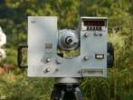
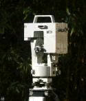
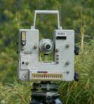
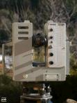
This web-page lists some electronic tachymeters built after 1960, concentrating on models built by the company Zeiss in Oberkochen,
then West-Germany. These were amongst the first compact tachymeters that used reflected optical pulses (EDM , Electronic
Distance Measurement). This technology evolved into the 3D laser-scanners and handheld laser range-finders of today.
Sub-topics can be selected by clicking on the list at the left side.
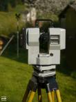
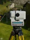
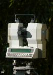
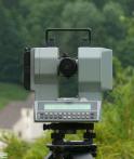
Parameters of some electronic tachymeter made by Zeiss, Oberkochen
parameters of some legacy Zeiss electronic tachymeters
| type
| Reg Elta 14
| SM4
| Elta 2
| Elta 42
| Elta 3
| Elta 4
| Rec Elta RL
| Rec Elta 13
| Rec Elta 15
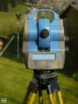
| Elta S10
| Elta S20
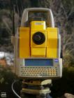
| Trimble 5603 DRE200+
with Zeiss interface unit
|
| images
| 
|
|
|
|
| (economy version of Elta 3)
|
|
|
| (precision version of S20)
|
|
|
| series
| 1st
| 2nd
| 3rd
| economy branch
| "E series"
| "Rec-Elta series"
| "S series"
| ?
|
| manufacturer
| Zeiss (West, Oberkochen)
| Zeiss (unified, Jena)
| Zeiss/Trimble (Jena)
| Spectra-Precision/Trimble (Sweden) and Zeiss (UI)
|
| approximate year of production
| 1968+
| mid 1970
| 1978+
| early 1980 ?
| 1985+
| 1985+
| 1990+
| 1990+
| 1993+
| 1998 - 2000 ?
| 2001+
|
| nominal angular precision
| 1 mgon (3.2″)
| 1 mgon (3.2″)
| 0.2 mgon (0.6″)
| 5″
| 1.5″
| 3″
| 1.5″ V, 2″ H
| 1.5″
| 3.0″
| 1″
| 3″
| 3″
|
| angular compensator
| one axis
| ?
| at least one axis
| -none-
| two axes
| one axis
| ?
| two axis
| two axes
| two axes
|
| distance precision
| ?
| ?
| 5-10 mm + 2ppm
| 5-10 mm + 2ppm
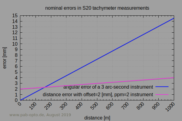
| 3mm + 2ppm
| 3mm + 3ppm
| 5mm + 2ppm
| 2mm + 2ppm
| 3mm + 2ppm
| 1mm + 2ppm
| 2mm + 2ppm
| 3mm + 3ppm
|
| telescope magnification
| 25x
| 25x
| 30x
| 28x
| 30x
| 30x
| ?
| 30x
| 22x
| 30x
| 30x
| 26x (30x optional)
|
| options
| -
| -
| pluggable firmware and storage modules
| -
| external laser pointer
| -
|
CM/CMS version with motorised axes, slip-ring
|
Track (co-axial CCD for prism lock/track),
Arc (wireless),
Space (extra sensor to find prism)
| wireless control, laser pointer, tracker (both not co-axial)
|
| optical sighting indicator for stake-out work
| no
| red/green: left/right
blink frequency: distance
| yes
|
| reflector-less
| no
| yes
(prism not recommended under 50m)
| no
| yes
|
| built-in optical plummet
| no
| yes
| no
|
| angular encoder type
| relative
| absolute
|
motorised axes
"robotic"
| no
| CMS version
| yes
|
| user interface (hardware)
| rotary/dip switches
Nixie tubes
| rotary/dip switches
LED 7-segment
| rotary/dip switches
LED 7-segment
| rotary/dip switches
3x LCD
| two 4 line x 9 character alpha-numeric LCDs
3 buttons
| 240 x 38 pixel,
4 line alpha-numeric LCD
24 keys
| 320 x 80 pixel LCD,
QWERTY keyboard
| 320 x 80 pixel LCD,
QWERTY keyboard (detachable)
|
| op-sys
| Zeiss firmware
| MS-DOS
|
| internal storage of points
| no
| yes
MEM200,MEM800
| ?
| no
| yes
|
| PC interface (hardware)
| 5bit tape puncher
| none
| MEM modules, RS232
| RS232 , 1200,2stop,7bit+odd
| RS232 , 1200,2stop,7bit+odd
| RS232 , configurable
| RS232 , configurable
PCMCIA flash card, optional wireless
| RS232 , configurable
PCMCIA flash card
|
| original battery pack
| external NiCd 12.5V 17Ah
"Ramert DEAC 12 Z D19"
| Zeiss 708110 7.2V,
700911 7.2V
| Zeiss 708152 4.8V 1800mAh NiCd,
705351-9020 4.8V 2400mAh
| Zeiss 702710-9030, 6V 3500mAh NiMh
| ?
|
| original charger
| ?
| Zeiss LG 4, LG 7, (?)
| Zeiss LG 9
| Zeiss LG 20
| ?
|
| replacement cells
| probably any 12V source with suitable current
| 6x 1.2V NiCd size C
| 4x NiCd, diameter 26mm, height 50mm, e.g.:
Sanyo/Panasonic
KR-CH(2.5) 2500mAh or N-3000CR 3000mAh
| 5x NiMh
e.g. Panasonic HHR380A-LF 1.2V 3800mAh
| 12V gel/AGM Pb-battery
|
case
L x W x H
[cm]
| Al
-
| dark grey plastic
46 x 38 x 25
| yellow plastic
55 x 40 x27
| yellow plastic
41 x 22 x 29
| light grey plastic/Al
50 x 37 x 25
or yellow plastic
| yellow plastic
47 x 42 x 28
| yellow plastic
38 x 30 x 50
|
Zeiss (West) had built a lot more models: For example the early S11 (Elta14 w/o electronic angular reading), the Eth 2/3/4 (on the market
at the same time as Elta2/3/4 "E-Series", with a different display, the same type of chassis shape, but without distance measurement),
Elta 13, Elta 6, Elta 40, Elta 46, RecElta14, C30 (successor of the S20 ?, no QWERTY keyboard), or the "R" (Routine) family, R45,R55,R50,
an economic newer series, already built in partnership with Spectra Precision.
The names of the instruments by Zeiss Oberkochen can be a bit confusing:
The names "Elta 2", "Elta 3" and "Elta 4" may refer to instruments in different series: There are "Elta 2,3" in the first series, after the
initial Elta14 , and the newer "Elta 2,3,4" models of the "E-Series", as shown in table above. They have radically different internal
electronics, battery voltages and user-interfaces. With both series, the lower number has better angular resolution and a higher price.
Similar, a fellow-up to the "SM4" was, according to a Zeiss publication of 1978, named "Elta 4" too at the time. Additionally to the "SM4" it
had electronic angular read-out and was marketed as the low-precision version of the then "Elta 2". So the name "Elta 4" may refer to one of three
completely different instruments, depending on the decade of its manufacturing.
The rather coarse "Elta 42" (and "Elta 46" ?) had been a short-lived low-cost branch in the Zeiss product spectrum, - I have to update this
description here with some new information ASAP.
And furthermore, in parallel to Zeiss Oberkochen (West Germany, BRD, ''Federal Republic of Germany''), there had been a product range of Zeiss
Jena (East Germany, DDR, ''German Democratic Republic'') between 1946 and 1999 as well. Zeiss Oberkochen and Zeiss Jena had been fierce
competitors on the world market during the era of the "Cold War".
There are a couple of symmetries: Zeiss West supplied the Elta14 to the Olympics (distance measurements in javelin throw, etc) in Munich 1972 and
Zeiss Jena had their tachymeters at the Olympics in Moscow 1980. In their time, both had been at the high-end of electro-optics.
For older S10/S20 with "PC-Version 1" hardware, there are issues with CFCARD-to-PCMCIA adapters (see section on PCMCIA). And the older
"PC-Version 1" hardware is terribly slow, likely due to a very slow 86286 CPU: A lot of patience is required when operating an S10/S20 with
"PC-Version 1" in the field.
Update: Most instruments of my collection have been donated to the archive of Zeiss Jena in May 2022.
common features of Zeiss electronic tachymeter
- telescope image upright
- selectable angular units: GON or 360 degrees (DMS).
- measurements in both telescope positions
common features of Elta 3/4/Rec/S20
- TOF-to-distance calculation parameters: atmospheric pressure, temperature, optional correction factor, prism constant
- communication via RS232 on DIN 41524 connector,
pin-layout,
(stationary connector via slip-ring except on Elta-3)
- LCD displays, readable even in bright light. Instruments before 1980 had small red LED 7-segment displays.
some accessories
- 704105-9901 might be another zenith ocular prism
- 704105-9902 zenith ocular prism for Rec-Elta. Note: Fits Elta E-series too, if last ring at tube is screwed off
- 704116 zenith ocular prism for Rec-Elta (?)
- 704137 front filter for sun observations, Rec-Elta
- 708146-9901 external battery 6V 7Ah
- 708155 rechargeable battery 4.8V 2.0Ah
- 708177-9350 cable, combined data and external power
- 708186-8500 counter weight for Rec-Elta, if external power is used
- 708186-9100 optional slip-ring for Rec-Elta
source: Zeiss manual Rec-Elta
The special case of the Trimble 5603 with Zeiss Control-Unit (Elta-CU)
The Trimble 5603 is the odd one on this list: The base unit was made by Spectra Precision AB, Sweden, and has, as far as I know, nothing to
do with Zeiss. Notably, some details and concepts differ: e.g. the motor drive of both axis are different to the S20 (worm-gear with slip clutch at
5603, radial tooth gears on S20), the 5603 doesn't have a built-in optical plummet, it lacks removable batteries (when using the track
option), the ocular is off-centre indicating a different internal beam path, etc.
The Series 5600 by Spectra Precision (later Trimble) featured a modular design and it offered four different detachable user interfaces
units. One type of these units was marketed as Zeiss Elta / Open System Control Unit (Elta-CU), carries a Zeiss logo and looks
the same as on the S20. Available programs on this unit either have a look&feel of Zeiss Elta or of Trimble. Users of an Elta S10/S20
will find this identical to operate. A nifty idea to separate the software look&feel from the underlying hardware.
The Zeiss-CU is "Made in Sweden".
My 5603 came "naked", without batteries, cables or remote control, hence it needed some background research:
The type of push-pull-4-pin connector used on the Trimble 5603 and its Zeiss user-interface is Hirose HR10A-7P-4P (low-cost version) or
Hirose HR10-7P-4P , e.g. available from
Digikey.
The socket at the 5603 dismounts easily and reveals a little PCB with a 3.5A SMD fuse, from which the pin functions can be deduced.
Note that the number on the PCB close to the socket is not the pin number of the Hirose socket.
This wiring, shown in the image, works for me (see photo), but no warranty for the pin numbers (see Hirose HR10_catalog.pdf):
pin4: GND green/blue; pin3: 12V yellow/red; pins 1,2 are likely the RS232 interface.
This type of socket is, IMHO, mechanically a little frail for this task and it may break if the cable is pulled strongly by accident. This
specific socket showed a crack already, when viewed under a microscope. It is a good idea to add a strain relief at the tripod close to the
5603. But of course, that depends on where the battery is placed.
Power consumption was found to be 1A to 1.4A at 12V DC (12-17W). The 5603 is sensitive to under-voltage and draws a surge at power-on:
It required at least 12.4V to boot when connected via a 1.5m cable of 0.14mm cross-section, powered by a professional power-supply.
Booting did fail on a consumer-grade lab power-supply, which couldn't balance the initial power surge, although it is rated to drive 3A maximum.
If an Elta-CU does boot when powered directly, but does not boot when powered by the Trimble main connector, it could be a problem with
the initial current surge. The maximum cable outer diameter of the Hirose plug is 5mm, which limits the wire diameters and hence the cable
length.
For those not happy to do soldering themselves, - there's a market out there offering ready-made cables and custom batteries.
The Elta-CU has one internal NiMH back-up battery, 5x AAA-size, 6V , and 2x 3V Li coin-cells, soldered on-board.
The correct procedure for replacement is yet unclear, - disconnecting them may void RAM-stored programs or parameters, and may
brick the 5603.
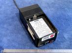
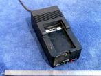
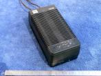
Zeiss batteries and chargers
some Zeiss charging stations for Zeiss-tachymeter battery packs
| station name | LG4 | LG6 | LG7 | LG9 | LG10 | LG20
|
| number | 708105 | 708112 | 708107-9901 | 708150 | | 708100
|
| image
| 
| 
| 
| 
| charger for REC500,
according to Zeiss list
| 
|
fitting battery
type number
| 708110 | 708111 | 708110,700911 | 708151,708152 | - | 702710-9030
|
| cell type | NiCd
| NiMh
|
| number of cells | 6 C-size | 5 AA-size | 6 C-size | 4 C-size | 4 AA-size | 5
|
| nominal voltage [V] | 7.2 | 6 | 7.2 | 4.8 | 4.8 | 6
|
| photo of battery pack
| 
| 
|
| 
| -
| 
|
Maintenance, Repair, Overhaul (MRO)
The situation with legacy Zeiss-West instruments is worse than the one with Swiss-made legacy
Kern instruments, where enthusiasts run a detailed and open archive.
Another better example are the archives of Wild-Heerbrugg.
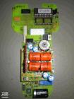
internal back-up batteries in Elta-3, Elta-4 E-Series
The following internal batteries have been found in an Elta-3 E-Series, presumably they power the SRAM with the calibration data.
Hence loss of the Lithium power could mean that the instrument is bricked.
They are located on the inner side of the PCB that is mounted underneath the socket of the main external battery.
Exchanging them requires de-soldering the contacts and may require an auxiliary power supply while doing so.
- 4x Ni-Cd batteries, type Panasonic P-11AAH , 1.2V, 110mAh
- 1x Lithium 3V, type Varta CR 1/2AA 6127
Internal batteries on an Zeiss Elta3 E-Series
| 
|
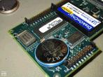
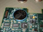
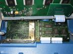
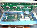
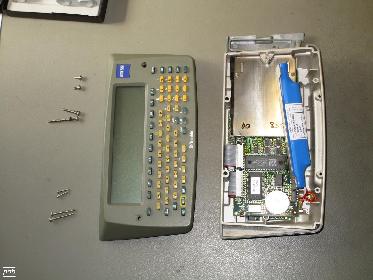
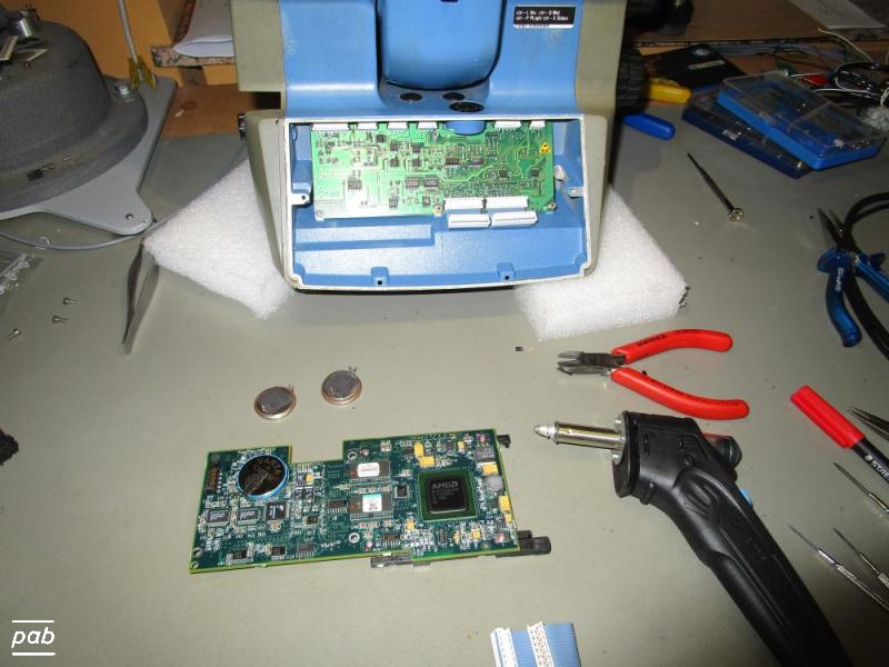
internal back-up batteries S10, S20
For an S20 with PC-board revision 2:
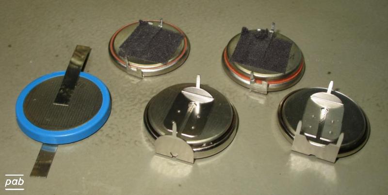
Two internal Li 3V batteries were found: CR2430 (280mAh) and CR2450 (560mAh) .
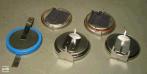
There are different types of connectors available with this size of battery: pins, dual pins, lugs (see image).
A little tweaking may be required, to replicate the pin positions and height of the mounted battery.
The exact purpose of these batteries remains unclear: RT-clock, SRAM, ''NVRAM'' ?
At least the system was boot-able with the old batteries, when each was at 0.2V instead of their nominal 3.0V . After replacing one-at-a-time,
it still booted OK. With new batteries, the date and time remain updated, even when the NiMh battery pack is removed.
Exchanging them is relatively straight-forward with a little solder practice, but having vacuum de-soldering equipment at
hand is a plus. Apparently one GND pin is connected to the GND plane without proper "thermal relief" on the PCB common glitch), so it
requires a little more soldering power.
Internal CR2430 Li batteries on an Zeiss S20 PC-board revision 2

| 
| 
|
general maintenance problems with legacy electronic tachymeters
Keeping a legacy electronic tachymeter in working condition becomes increasingly problematic. Compared to their non-electronic
forerunners they pose a few extra problems:
- The lack of documentation about the electronics and firmware constitutes the biggest problem. It makes in-situ replacements
with newer components difficult, if not impossible.
This seems especially problematic in the case of Zeiss tachymeter hardware, since both Zeiss (Oberkochen or Jena) and Trimble seem to
distance themselves from these legacy products. Which is bit sad, regarding their high quality.
If you can shine some light on this with inside knowledge, please contact author of this web page.
- declining availability of electronic components for a 1:1 replacement: LCD display, CPU, NVRAM, ROM,
the exact type of IR-LEDs and laser-diodes in distance measurement and the illumination used in the angular encoders
and compensators. Some CPU chips aren't even marked, so the type remains unknown.
- degenerating plastic materials (likely to happen, even for sturdy materials like ABS-GF on the S20) and sealants
- ageing internal back-up batteries that power SRAM containing
calibration data. Apparently these were used before true "non-volatile"
NVRAMs became available.
When an instrument looses its calibration data, it is very likely "bricked".
Replacing an internal battery (e.g. Lithium 3V) can be difficult, since they are soldered and auxiliary power has to be supplied
while the battery is changed. - Assuming that the specific type of battery is still available.
- internally, the delicate slip-rings and encoder glass plates are not further encapsulated.
Glass plates of angular encoders are fragile and sensitive to the touch of a finger.
One finger print can ruin them.
- general lack of internal documentation: assembling procedures, calibration procedures, circuit diagrams, engineering drawings.
Some maintenance manuals are available in the Zeiss archive, but their list is not complete for their western tachymeters yet.
No circuit diagrams or engineering drawings seem to be available at all.
Update 2023: AFAIK, the buyer of the Zeiss geodetic instrument section, Trimble Inc. , now blocks the Zeiss archive from making
old internal drawings available via their website. - Even for the very old E-Serie of 1980/90. It seems a typical idea bred by
corporate lawyers, who aren't aware what they're dealing with from a technical point of view.
It certainly makes support hard to impossible, even for private individuals.
- theoretically, it seems possible to completely rip the existing electronics from a legacy Zeiss tachymeter, just use the
optics and mechanics, reverse engineer the cabling of the angular encoders and (maybe) the compensator and replace the
electronics with newer hardware. Including the distance measurement, since dedicated chips for time-of-flight (TOF) are available.
Personally, I would trust the mechanical precision of any Zeiss instrument for a very long time.
If you go for that, let me know, - thanks.
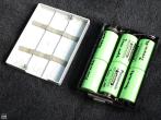
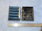
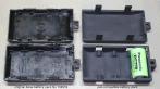
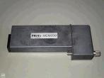
project to get a compatible battery pack for Elta-3, Elta-4, Elta-RL
substitute for Zeiss 708152 NiCd battery compartment using STL ''3D printing''
|
Work is currently (2016) under way here on a mechanical replacement for the original 4.8V battery packs.
The original packs consist of two extrusion molded halves, glued together. Their shape is deteriorating after opening and re-sealing
multiple times for exchanging expired cells.
This replacement uses screws to mount the two halves, which makes the upcoming (?) replacement of cells easier. That said, the
availability of NiCd cells is probably ending at some time in the near future. NiMh cells could be a replacement,
but require a different charging technique, and hence a different charger.
Using USB power-packs to supply Elta E-Serie instruments may work. The voltage level is 4.8V to 5V in both cases. Care must be taken not
to reverse polarity, it would be unwise to assume any built-in protection circuits. No experience on my side with this, so I can't advise on it.
PCMCIA cards for S10,S20,5603
The Elta 10,20 , RecElta and Trimble5603 (with Elta CU) use PCMCIA storage cards. These PCMCIA cards became somewhat rare around the year 2010.
For the PCMCIA slot (aka "PC card"), a CF-card-to-PCMCIA adapter is an
alternative. New storage cards in Compact Flash format (CF cards) are still available
today (2018), while new PCMCIA memory cards (SRAM) are exotic (yet still used in some automation systems), rare and expensive.
However, a CF-card with a PCMCIA adapter works only on an S10/S20 with "PC-Version 2". Although both "PC-Versions" list
Zeiss "SW version 1.43" , the older "PC-Version 1" hardware does not work with adapted CF cards and seems to accept PCMCIA SRAM cards only.
Booting an older model with a CF-card was found to stall sometimes, while an original 1MB SRAM card worked. As a rough indicator, the
update to hardware "PC-Version 2" may have happened around serial number 110000.
Apart from the issue with the PCMCIA adapters, the older "PC-Version 1" hardware is terribly slow, likely due to a very slow 86286 CPU. A
lot of patience is required when operating an S10 with "PC-Version 1" in the field.
As said, PCMCIA/PC-card SRAM cards (e.g. 1MB) behave differently and can be difficult to read/write on Linux. Even on an
older laptop with native PCMCIA/PC-card slot, reading/writing hasn't worked for me. Industrial USB-to-PCcard converters do exist, e.g. by
CSM, since
some legacy industrial controls still rely on PC-cards. However, they are expensive.
Serial communication is an alternative way to upload/download data to/form an S10/S20 instrument with "PC-Version 1" hardware.
Good news: The CF-to-PCMCIA adapter does work on the newer Trimble 5603 as well.
internal PCMCIA I/O PCB beneath S10/S20 keyboard
| PC version 1
| PC version 2
|
| 
|
Formatting of CF-cards on Linux for acceptance by the MS-DOS in the S20 needs fiddling of parameters for "mkfs". These were found to work with
version 3.0.13 of mkfs.vfat, for an S20 with a "PC-Version 2" board:
mkfs.vfat -n tachy3 -F 16 -h 32 -s 16 -R 1 /dev/first_partition_on_cfcard
The "-h 32 -s 16" parameters are the critical ones.
Inout/Output components and storage hardware
Following the tape-puncher of the Elta 14 and prior to affordable laptops, Zeiss offered exchangeable memory modules for data storage in
the field. A second way for storage were external storage units that interfaced with the tachymeters through RS232:
memory modules MEM100, MEM200, MEM800
The main reason for an in-the-field automated data storage is to avoid errors when communicating and writing down numbers manually. Faster
speed is a benefit as well. Hence, once electronic reading of angular and distance values became technically feasible, their automatic
storage was the next logical thing and constituted a big push forward in practical surveying.
The first in-the-field storage system of the then Elta-14 consisted of a 'portable', battery powered, 5bit tape puncher. The storage
technology of the outgoing 1960-ties, used extensively in teletypers of the period.
These memory modules followed and offered an intermediate, optionally per-project, data storage between the tachymeter in the field and the
computer at the office, without the need to carry the bulky computer equipment of the time (or a tape-puncher) into the field. They were sort
of the "memory card" of the period.
Later the REC500 offered a compact "tablet-like" solution with an enhanced user interface, and the need for these memory models declined.
Note that the later E-Serie generation (see images above) doesn't have this memory slot.
According to a publication of Zeiss Canada from 1981, there had been a MEM100 module as well, supposedly a predecessor or low-capacity variant of
the MEM200. The text states the capacity as "200 and 400 data-sets", and life of the buffer battery as "1 week" between charging.
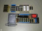
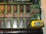
The Zeiss MEM200 was a pluggable memory module for the second-generation Elta2. It
features 12x TC5504P-1 Toshiba CMOS static RAM, 4kx1 bit each (roughly made around 1981) and an internal backup battery. Also included are 2
EPROMS and a Harris M3-6100-9 CPU, which, according to the web, runs 12bit @ 4MHz. On-board quartz is 2MHz. Plus some DIL ICs.
Interestingly, on this MEM200, one TC5504P-1 had been replaced during its active time of duty. The 14-pin "Centronics"-style connector
(similar to IEEE 1284) has the 2 rows connected in parallel, hence 7 lines for signal and power. Likely a multiplexed data-transfer. - ?
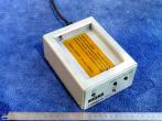
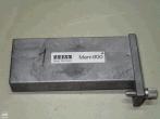
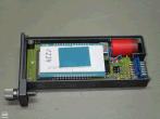
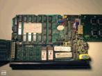
The Zeiss MEM800 was a pluggable memory module and supposedly the successor of the MEM200. The I/O connector of a MEM800 is the same as on
a MEM200.
It features unlabelled RAM chips on an extra PCB (the white 'bricks' in the photo) and an internal backup battery, likely the same Varta
4-60DK @4.8V as the MEM200. Visible futhermore are a single EPROM, Texas-Instruments TMS70C00BNA CPU and 4 SMD latches, drivers and bus
multiplexers. The TMS7000 had been an 8bit CPU released in 1981, featuring optional microcode customisations stored in CPU ROM.
Zeiss MEM200, MEM800 memory modules
| MEM200
| MEM200 internals
| MEM800
| MEM800 internals
|
| 
| 
| 
|
interface units DAC100, REC100, REC200, REC500
The Zeiss DAC100 was, according to a Zeiss publication of 1978, the first data conversion unit to read MEM memory
modules, primarily intended to be used at the office. It interfaced to computers or printers via a RS232 serial connection.
According to a picture in that Zeiss publication, it looked like an early desktop calculator, there's no actual unit in this collection (yet?).
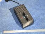
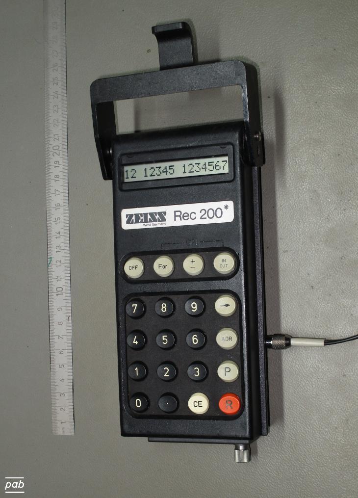
The Zeiss REC200 was a follow-on data conversion unit to transfer from/to MEM modules. and charge their internal
back-up battery.
It can either log data from Zeiss tachymeters via RS232 in the field, or transfer the data to computers at the office.
Powered by battery type Zeiss 70811 or a 12V DC input. The 70811 battery type fits in the Zeiss LG6 charger.
Display consisted of a 16 character, single line LCD, with user input via 9 function-buttons and a numeric keypad.
Getting it to work is somewhat cryptic without consulting the manual.
The RS232 interface uses the same DIN 41524 connector as on the tachymeters (see above for a pin list).
According to a publication of Zeiss Canada from 1981, the Zeiss REC100 was similar to the REC200, but without the LCD display.
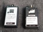
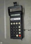
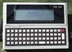
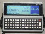
The Zeiss REC500 was a newer, portable, ruggedised hand-held computer, used for data storage and management with Elta models
that did not have on-board data storage, but an RS232 serial port. Effectively it replaced the storage function of the older MEM modules
with a much nicer and more powerful storage and user-interface.
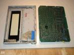
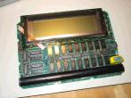
Two hardware were used: The older model "Husky 352KEL", model 114K or newer "Husky Hunter", model H-2922, both manufactured by "Husky
Computers Ltd" in Coventry, UK.
The newer features a graphics-capable LCD display, QWERTY keyboard, one 25-pin sub-d RS232 port and a 4pin Lemo
socket for power supply and charging.
According to its manual of 1986, it runs CP/M on a Z80 CPU and a BASIC interpreter,
Other internal parameters (CPU,RAM,NVRAM,etc) not (yet) known to author. The manual mentions an additional internal NiCd battery and
seal dimensions of 1.5mm x 30mm for the AA battery compartment.
Wikipedia article on Husky computers
Zeiss interface units
| REC200
| REC500
|
| earlier version
| later version
|
| 
| 
|
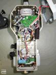
REC500, Husky early version, internals
 |
|  |
|  |
|  |
|
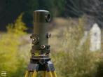
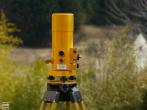
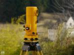
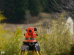
Optomechanical Theodolites by Zeiss Oberkochen
parameters of some legacy Zeiss opto-mechanical theodolites
|
| Tachytop (Bussole)
| Th 3
| Th 2
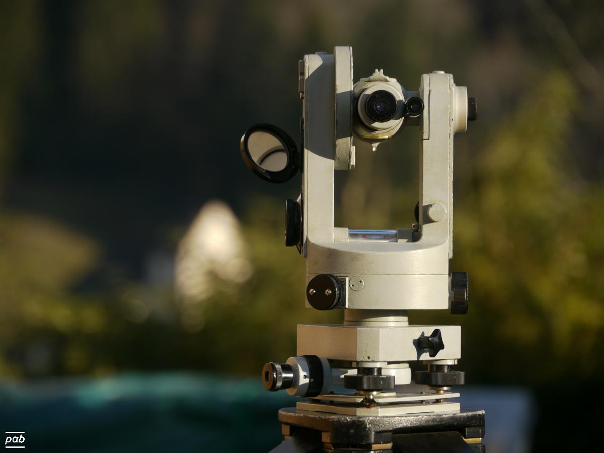
| Th 42
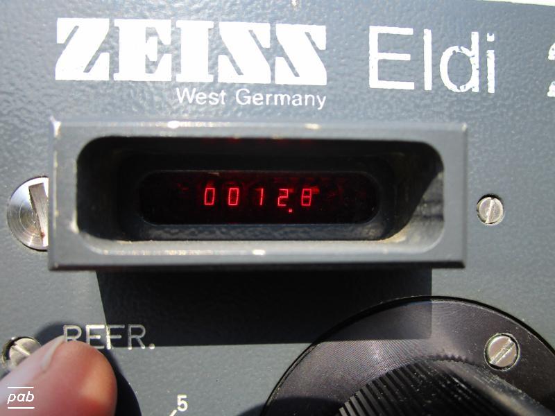
| Th 42 + Eldi2
| Rta 4
|
| images
|
|
|
|
|
| 
|
| coordinate display
| coming soon
| 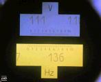
111.17 GON vertical, 136.645 GON horizontal
| 
| 
(image quality and field-of-view limited by camera.)
Reads 98.815 GON vertical, 326.735 GON horizontal
precise for a layman's eye to 0.002GON, about 6″
|
| manufacturer
| Zeiss (Jena)
| Zeiss-Opton (Oberkochen)
| Zeiss (Oberkochen)
| Zeiss (Oberkochen)
|
| approximate year of production
| ca 1930-1950 ?
| ca 1953-1969
| ca 1960-1970
| ca 1960
| ca 1960 ?
| ca 1960-?
|
| nominal angular precision
| 0.1g
| 1'
(0.1' with micrometer)
| <1"
| ?
| ?
| 3″
|
| angular compensator
| -
| -
| one axis
| one axis
| one axis
| one axis
|
| angular reading [GON]
| 1.0g
| 0.1g
0.01g micrometer
| 0.0001g (0.3")
| 0.01g
| 0.01g
| 0.01g
|
| angular estimate [GON]
| 0.1g
| 0.01g
0.001g micrometer
| -
| 0.001g
| 0.001g
| 0.001g
|
| distance precision
| -
| -
| -
| -
| Eldi2 ± 5mm, ± 20mm
| 5-20cm / 100m (500ppm)
|
| telescope magnification
| 12x
| 25x Apochromat, coated,
inverted image
| 30x
| 25x ?
| 25x ?
| 25x Apochromat, coated
|
In order to show the vertical and horizontal scales in one display, the theodolites used an impressively complex optical path within the
instrument. Sub-second theodolites like the "Th 2" also have a rather fascinating ''vernier scale'' method for adjusting and reading
sub-second angles.
One way of distance measurement is to use the view-angle that a distant vertical rod subtends in the view finder of the theodolite. This is
easy, but is limited to a ''few dozen meters'', beyond that it becomes increasingly difficult to read the rod markings and the required rod length
becomes too large. For non-horizontal view directions (''down-hill'' or ''up-hill'') correctional factors have to be applied.
The principle is mostly used for construction work in domestic-house-size building projects.
Some theodolites (e.g. the Zeiss Rta4) do have a very clever mechanical automatic adjustment to measure horizontal distances even when
viewing the vertical rod up-hill or down-hill (the so called ''reduction'' of distances).
A "bussole" theodolite is effectively a precision compass plus an additional vertical angle reading. It is used if no second point is
in sight as horizontal reference. Azimuth readings are comparatively coarse and relative to
Magnetic North. The angular offset to "True North", the
Magnetic Declination, depends on the location on the Earth and is
not constant over years. All magnetic materials (e.g. steel) must be kept well clear of the bussole while taking readings.
A Gyrocompass is an alternative that orients itself to "True North" automatically.
Parameters of Eldi 2:
910nm, 15MHz/150kHz (two ranges, 700m, 1000m), 6-9V DC, 5W
Nominal error: ± 5mm @ 700m range (7ppm), ± 20mm @ 1000m range (20ppm)
Due to the modulation frequencies, the measured and displayed distance is correct up to 1000m, for longer distances there's a manual correctional
procedure.
Source: Zeiss manual G70-165-d, 1977
Optomechanical Levellers
parameters of some legacy opto-mechanical levellers
| manufacturer
| Zeiss Oberkochen
| Zeiss Jena
| Nestle
|
|
| Ni 2
| Koni 007
| Ni 007
| Nan 2024
|
| images
|
|
|
|
|
| telescope magnification
|
| 31x
|
|
|
| compensator
| yes, damped
|
| telescope image
| upright
|
| instrument precision
| 0.5mm/km
| 0.8mm/km
0.5mm/km according to test by Zeiss-West (!)
| 3mm/km
|
| extras
| nonius (20′) at
horizontal angle
| micrometer plate
|
|
| introduced
|
| 1959
|
|
|
Devices made by other companies
other legacy opto-electronic distance measurement (EDM)
parameters of other legacy EDM equipment
|
| AGA Model 6A
| HP 3800B
|
| images
| 
|

|
| instrument precision
| ?
| 5mm + 7mm/km
|
| instrument range
| ?
| max 3km (triple prism)
|
| readings
| potentiometer
| numerical decade knobs
|
| approximate year of production
| 1950-1960 ?
| 1969-1975 ?
|
| power supply
| ?
| rechargeable battery
12V, draws approx 1A
|
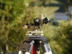
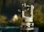
Both are non-coaxial instruments, the telescope and the range finder are not at the same vertical position. Therefore, HP offered a prism
with a vertical post and instructions to aim the telescope above the prism.
Parameters were taken from HP's "3800B/3801B Operating Manual", Part No 03800-90004, printed ca 1972.
Hewlett-Packard 3800B distance meter
This 3800B actually still works, straight out of the box, even after more than 50 years. The only refreshed part was a new 12V lead-acid
battery. A test gave a reading of 13.12 m , compared with a modern Leica Disto 13.22m.
Taking into account that the reference points of the 3800B and the prism got only estimated quickly crudely, and
that there are some fluctuations in the zero-indicator of the 3800B, both values agree within reasonably error bounds.
Some overhaul of potentiometers and dials may stabilise the reading.
The 3800B requires a specific manual procedure to select each the 5 dials to get a complete distance reading.
Very likely the 5 different ranges use 5 different modulation frequencies for the IR laser-diode.
Correction for air pressure and temperature is done externally and manually: The HP3800B has an external potentiometer located at the battery
pack to set a correction factor for both, and a chart to read the correction factor depending on temperature and pressure.
The 3800B has no way to set a "prism constant", apparently meant to be used with the original HP prism only.
This 3800B came with two adapters to a tribrach: One fits Zeiss-style tribrachs (one central cylinder), one is used for Wild-type ones (3 pins).
See also: NOAA web-page on the 3800B,
and americanhistory.si.edu.
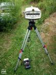
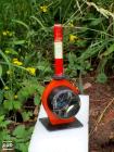
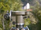
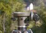
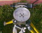
compass theodolite by Ertel
Ertel compass theodolite
| images
| 
|
| instrument precision
| reading approx 3 mGON
|
| telescope magnification
| 12x (inverted image)
|
| distance factor
| 100
|
| approximate year of production
| 1950 - 1970
|
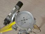
This type of compass theodolite was built by Ertel in Puchheim, Bavaria. Its telescope image is inverted with horizontal
stadia lines, optionally with a right angle prism at the ocular. According to a very helpful guy who had worked at Ertel, two variants had
been manufactured: A grey painted standard model, and an identical, but dark-green painted one for the military. Some serial number start
with the prefix "FB" for "Forst-Bussole", ("forestry theodolite"), although this prefix is found in the serial number for some dark-green models
as well. On some models, the horizontal scale can be shifted ±15GON relative to the telescope axis, to allow setting of the local
value of the
magnetic declination, thus giving horizontal readings relative to
True North directly.
Due to the inverted telescope image, the instrument is best used with vertical rods that have the height numbers printed up-side-down.
Apart from a serial number, there's no model name or type mentioned on the instrument.
These particular examples had been used in federal forest management and building of forest infrastructure in Northern Germany,
and in their training classes.
The swivelling interface to the head of the accompanying special, non-ferrous, tripod allows levelling the theodolite.
The non-ferrous material ensures low or zero magnetic deviation. Notable is the
non-standard screw between tripod and theodolite, featuring a metric fine-pitch M15x1.5 thread. The screw and the non-flat head of the
tripod make these Ertel tripods incompatible with other theodolites.
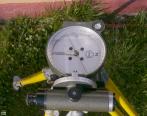
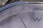
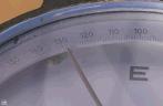
Note: The GON values on the horizontal circle increase anti-clockwise, with the East "E" label printed to the "left" of North. This may be
counter-intuitive at a first glance, since compasses scales show angular values increasing clockwise, and West to the "left" of North. However,
both work correctly, and read the correct value. For example, 90°, 100GON, when pointed to the Magnetic East. Two positions of the
telescope are possible, see below.
General concepts in surveying
example of two-position telescope theodolite readings
two-positions of telescope at Ertel compass theodolite
|
| left-hand position
| right-hand position
|
sighting centred on
church lighting rod
|
|
|
| top view
|
|
|
detail of
North end of needle
|
|
|
horizontal reading
North end of needle
| 328.5 GON
| 128.5 GON
|
Most theodolites and tachymeters allow to focus on the distant target using either of two positions of the telescope. The main advantage is
to intrinsically cross-check the instrument and get an estimate on its errors. Secondly, it can identify errors in manual reading or
alignment. With manual reading, the advantage of the GON angular units becomes obvious: The difference between the two readings is 200GON,
which is easier math than adding/subtracting a value of 180deg. Motorised tachymeters offer automatic measurements with both telescope positions
and cross-check these automatically with pre-defined error-bounds.
The above example of an Ertel theodolite is slightly unusual, as the axis of its telescope is not centred above its vertical axis, but has
an 8 cm offset. The parallax error caused by this in the above example, with a distance to the church of roughly 360m, is atan(0.08m/360m) = 14 mGON ,
which is about a factor of 20 smaller than the estimated precision (300 mGON) of the visual reading of its scale. Hence the parallax error
could be neglected anyway in this case. However, for objects closer, the average of the two telescope positions must be used to compensate
for the parallax error.
For theodolites with the usual centred-mounted telescope, a remaining 'gap' between the telescope axis and vertical axis constitutes an
instrument error which can be cross-checked by measurements in both telescope positions.
In general, with instruments where the full angular circle is readable, it is advised to read the angular value at opposite positions.
In the case of the Ertel bussole, this means reading both the North and South end of the needle, to increase precision and cross-check
for out-of-centre errors.
Historical remarks
The use of modern metal theodolites for surveying and constructions goes back well over 100 years. A brilliant example was the surveying
that led to the successful cut of the first Gotthard Tunnel in 1881, when the
two tunnelling crews met quite nicely spot-on inside the mountain.
Instrument precision went up over the decades, size and weight went down, and the handling was greatly eased for the surveyor (e.g.
electronic reading the scales).
A major revolution came with electronic distance measurement (EDM), which is the only way to measure distances over 100m fast and
accurately. Measuring survey distances by timing electromagnetic waves became available in the field around 195x. First by microwave, then
in the infra-red spectrum. After the first infra-red and combined instruments (like the "Elta 14"), the route was set to develop faster and
more compact instruments, leading to the indoor and outdoor 3D scanners of today (2010+, "LIDAR").
Another milestone was the introduction of prism-less tachymeters around 2000, which work with the reflected light off most surfaces. First
tachymeters needed a retro-reflecting prism at any distance, todays instruments
require a prism only for very large distances. The reflected signal off a normal dark grey surface in, say 100m, distance, is extremely weak,
and it is a respectable feat of electronics that today's instruments work with whatever low signal they get. For distances in the order of a
kilometre and more, prisms are still useful. If not for signal strength, they define the measured point exactly.
They are also used in "stake-out" work, when 3D coordinates are mapped to a 3D-point in the field.
The reading of angular values went electronic too, with the advent of electronic tachymeters. That alone greatly simplifies the surveying
process: Manual tables and logs were replaced by electronic storage of measured coordinates. The two positions of a theodolite, used at all
times to cross-check alignment errors of the instrument, can now be handled electronically and hence done automatically.
The units of GON and DEGREE are selectable in one instrument by software, before that, an instrument had either a hardware scale in GON or
DEGREE. Furthermore, electronic processing of angles and distance allows a direct conversion to Cartesian XYZ coordinates in the field and
XYZ coordinates of points can be directly exchanged with 3D CAD systems.
However, the ease of using a modern tachymeter still depends, like with their mechanical predecessor, on the skill of its manufacturer and
matching the preferences in handling by the surveyor. There are excellent graphical-user-interfaces (GUI) and there are bad examples.
Another point is the readability of the display in bright light:
While the LCD of an 1990 "Elta-3" looks a bit dated at first, it is perfectly readable under
any light condition, while a newer (non-Zeiss) tachymeter with a 5" touch-screen using the Windows operating system, made around 2005, is
in fact unreadable outdoors.
Sadly, Zeiss in Oberkochen apparently decided to bail out around the time when the first non-prism tachymeters became available. - Although
their "Rec Elta-RL" was prism-less, the newer "S20" was not - a bit weird. They first merged with Zeiss Jena after German
unification, then, apparently, concentrated the surveying work at Jena and after a few years sold their whole survey product line to
Trimble.
Nevertheless, their instruments still work impeccable for actual surveying work, - what you should expect from a product with a "Zeiss" logo.
And, after all, a prism is both nice and required to define a point during "stake-out work" (transferring 3D points from CAD-model to landscape).
In any case, the distance measurements is primarily one of time. To convert to distance with usable precision, the speed-of-light in the
atmosphere must be known with sufficient precision. And that depends on atmospheric pressure and humidity along the optical path.
In most geodetic applications it is deemed safe to assume that atmospheric conditions at the point of the instrument are the same as along
along the optical path. Hence atmospheric parameters must be recorded by the surveyor or the instrument, and then corrected for.
This was done semi-manually with first-generation instruments and fully automatically with the newer ones (e.g. S20).
The speed of light is roughly 33cm (330mm) per nano-second (ns, 10-9 second).
Hence, to resolve 1mm with time-of-flight measurement, the electronics need a time resolution of 1/330 = 0.003ns, or 3 pico-seconds (ps, 10-12
second).
A sinus signal with 1 pico-second (ps, 10-12 second) period has a
frequency of 1000GHz (109 Hertz), so electronics
have to handle signals well in the high GHz range. And they must be stable, compact and reasonably priced.
Which easily explains that practical use of this technology required the invention and mass-production of
transistors and smaller
integrated circuits.
Technically there are two ways to get the timing: Either by directly measuring the time between sending a pulse and the returning echo
(time-of-flight, TOF). Or by modulating the emitted light with a few hundred MHz and measuring the phase shift between emitted and returned
signal. This requires a set of different modulation frequencies in order to get a non-ambiguous solution.
With the second method, measurements take longer, but electronics are supposedly easier.
In surveying, Satellite navigation ("SatNav") has replaced tachymeters for most
routine work. From a Physics point-of-view, SatNav is based on exactly the same principle of measuring time-of-flight: SatNav times
microwave signals and hence distance between the point on Earth and a collection of satellites about 20.000 to 25000km away.
SatNav can be precise down to 1cm, which is pretty good compared to the distance of 20000km. But it does require correctional real-time
information about the atmosphere to achieve this.
Hence, for surveying, it typically needs an usable SatNav signal from multiple satellites and a mobile phone connection. These are
not always available: The SatNav signal is impaired by high rise buildings in cities, foliage inside a forest or underground (mining,
tunnelling), while rural areas may not have mobile phone coverage. Which is why traditional tachymeters are still in use and relied upon.
Angular units, small angles
basic angular units
| unit | symbol | units/revolution | unit for small angles | example
|
| GON | g | 400 | mGON (1/1000 GON) | 50.1371g
|
| DEG | ° | 360 | arcsec (1/3600°) | 45.1234° (decimal)
or
45°07′24.24″ (DMS)
|
| RAD | | 2 π | mRAD (1/1000 RAD) | 0.78755rad
|
Angles in DEG can either be given as decimal or as
degrees-minutes-seconds (DMS): A decimal value of 45.1234deg is roughly the same as 45°07′24″ .
NB: The German term "Grad" is the same as the English "degrees". GON is called "Grad", "Grade" or "gradian" in English. Hence most pocket
calculators allow a selection of "DEG,GRAD,RAD" for angular units.
The popularity of "GON" amongst surveyors is fraternised with rather quickly in the field when comparing readings of mechanical theodolites
in the two telescope positions: Adding or subtracting a value of "200" from the azimuth readings is quicker than dealing with "180". But
with the advance of electronic processing and data transfer, the choice of units became less relevant in practice. A second advantage is
that fractional GON values are always given in decimal notation, whereas fractional degrees can be given in decimal or in minutes/seconds,
leading to potential confusion. Outside surveying, the use of GON seems to have remained very rare.
One arc-second is also something of a watershed for the precision of an instrument: Theodolites used in average construction work have a
nominal precision of 3″-5″, while first-order country-wide surveying calls for ''sub-second'' precision.
Theodolites for astronomical observations and first-order surveying (e.g. Wild T4) have a precision of 0.1″ .
In comparison, a nautical hand-held sextant has a typical precision of a
few arc-minutes.
1 arc second (1″)
corresponds to 4.8mm at 1km distance. Or while, we're at it, to 1.9km at 400000km, the approximate earth-lunar distance.
conversion of small angular units
| | | deg | 1/1000 deg | arc-minute | arc-second | mrad | gon | mgon | object size at 1m | at 1km
|
| 1 deg | = | 1° | 1000 | 60′ | 3600″ | 17.45 | 1.11g | 1111 | 17.45 mm | 1.7 m
|
| 1/1000 deg | 0.001° | 1 | 0.06′ | 3.6″ | 0.017 | 0.0011g | 1.1 | 17.45 μm | 17 mm
|
| 1 arc-minute | 0.0167° | 16.67 | 1′ | 60″ | 0.29 | 0.0185g | 18.52 | 0.29 mm | 29 cm
|
| 1 arc-second | 0.00028° | 0.278 | 0.0167′ | 1″ | 0.0048 | 0.0003g | 0.3 | 4.8 μm | 4.8 mm
|
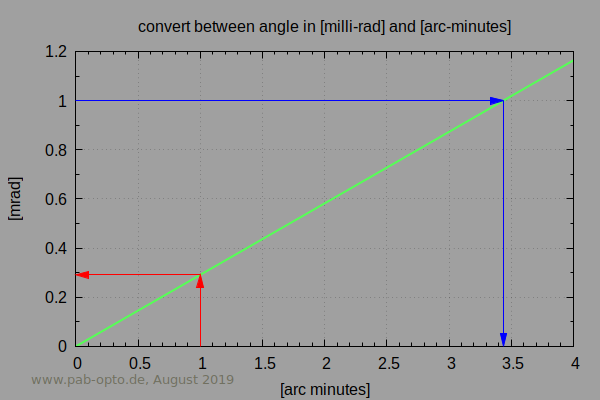
| 1 mrad | 0.057° | 57.3 | 3.44′ | 206″ | 1 | 0.0637g | 63.66 | 1 mm | 1 m
|
| 1 gon | 0.9° | 0.0009 | 54′ | 3240″ | 15.71 | 1g | 1000 | 15.7 mm | 1.6 m
|
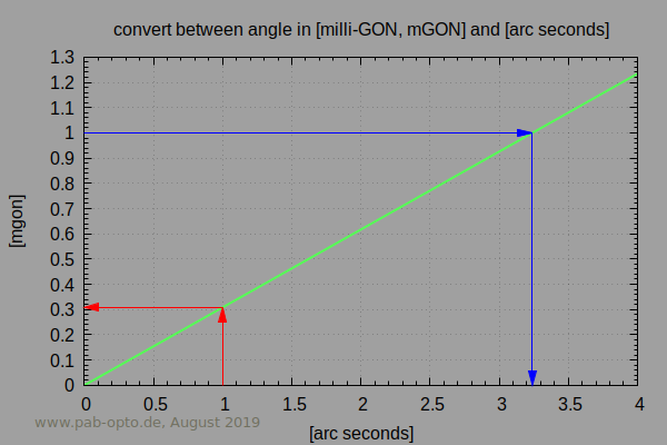
| 1 mgon | 900° | 0.9 | 0.054′ | 3.24″ | 0.0157 | 0.001g | 1 | 15.7 μm | 15.7 mm
|
|
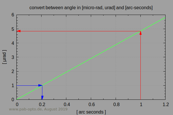
Angular units of [mGON] versus [arc seconds] :
|
Angular units of [mrad] versus [arc minutes] :
|
Angular units of [urad] versus [arc seconds] :
|
Angular accuracy and precision
As with any measurement, the nominal precision of the instrument does not solely warrant the "trueness" of a measurement.
Systematic internal errors may have been picked up since last calibration.
Handling errors can be of simple nature:
- typing errors in reference coordinates or reference angle when setting up instrument
- prism not exactly vertical above point
- wrong prism constant
- errors in air density for EDM
- instrument shifting due to tripod legs warming up asymmetrically in the sun, etc
Ways to reduce errors:
- measuring in both telescope positions
- cross-checking one or more known control points at start and end of the field work
- reducing statistical errors by averaging over multiple readings
- measuring the same target position from multiple reference points
- comparing two or more instruments
- checking EDM on outdoor field calibration sites, which had been set-up and used by officials
Cross-checking of results is highly advisable in any engineering or scientific work. Knowing the concept of
Accuracy and Precision is considered most helpful.
For example, the nominal angular and distance errors of an Elta S20 are, according to the Zeiss manual:
Miscellaneous and references
tripod UNC thread types
Tripods used in surveying use larger screws than
photographic tripods. The larger screws allow a central bore for an
optical sight downwards ("optical plummet"). One standard screw type is commonly used, except for some exotic legacy theodolites
(see Ertel example in "other brands") and quick-lock systems.
Like photographic tripods, this screw type is "Unified Coarse" (UNC).
And as usual with UNC, their specification consists of the outer diameter in fractional Inch
and the threads-per-inch.
For example, 1/4-20 specifies a diameter of 1/4" (6.35mm) and 20 threads-per-inch (1.27mm pitch).
By the way - UNC 1/4-20 is thus slightly incompatible with metric M6 (diameter 6mm, pitch 1mm).
UNC screws found at tripods, units [mm] rounded to 0.1mm
| thread type | outer diameter | pitch | drill size | tripod type
|
| UNC 1/4-20 | 6.4 | 1.3 | 5.1 - 5.4 | consumer camera
|
| UNC 3/8-16 | 9.5 | 1.6 | 8.0 - 8.3 | pro camera
|
| UNC 5/8-11 | 15.9 | 2.3 | 13.5 - 14.0 | surveying equipment
|
Worth to note that Unified Coarse (UNC) is not identical with
(British BSW) Whitworth thread, or British Standard Pipe (BSP).
Hence UNC 3/8 is not identical and not compatible to G3/8.
A bit confusing, since all use an "imperial" label based on a fraction of an Inch.
One difference is their thread angle: UNC uses 60°, Whitworth and BSP use 55°. The main parameters, like major diameter and pitch,
mismatch as well. - Welcome to the benefits of the newer, more systematic and, IMHO, easier metric system.
Trying to think fairly about the imperial system:
One advantage of a UNC screw over a metric standard screw of similar diameter
may be its slightly larger pitch:
UNC1/4 to M6: factor 1.3 , UNC3/8 to M10: factor 1.07 , UNC5/8 to M16: 1.15 . So one could argue that, with UNC, fastening of equipment to a
tripod requires less turns for the same screw length and is hence between 7% and 30% faster than it would be with a metric attachment. Most
notably with the smallest UNC1/4 screw.
quick locks types and tribrach systems
Early (pre WW-II) theodolites had been screwed onto a tripod directly. Newer system use a
tribrach as an interface between instrument and tripod:
Quick-lock system between tribrach and tripod offer faster mounting and a reproducible position, both in height
and, with the Kern and Wild types) orientation: Note the two pins on the Kern flange and the gap in the Wild flange, both enforcing a
specific orientation of the instrument on the flange. Compared to this, Zeiss featured a cylindrical "Zeiss bolt" as mechanical interface
between tribrach and instrument, which had no reproducible orientation around the vertical axis .
Most quick-lock systems offer to swap the theodolite with a target. The reference point of the theodolite is then at the same position as
the centre of the target (prism or mark).
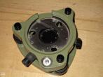
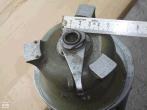
theodolite/tachymeter quick-lock mounts
| Wild | Zeiss | kern
|
|---|
| to come
|
|
The Kern type combined tribrach and tripod. It had a unique adjustment method: It used a vertical extensible rod to centre the tripod over
the reference point while adjusting the rod vertically over the point. This mechanical alignment has benefits and
drawbacks over the other two methods: Optically or using a wired plumb. With both the alignment over a reference point is a two step
procedure: Levelling the tripod and shifting it horizontally. The Kern method is slightly quicker.
Both Zeiss and Wild tribrachs are used between a theodolite and tribrach, with the tribrach attached to a tripod using standard UNC5/8-11
screws. The Wild quick-lock is still used widely today, it has become the de-facto standard. It offers considerable advantages over the Zeiss
mount, while being mechanically more complex.
disclaimer
Although data was compiled with care and cross-checked where possible, all data and parameters are supplied "as-is" without any
warranty.
We're not responsible for the contents of other websites, even if we link to them.
thanks & further reading
- Thanks to various professionals, some of them ex-Zeiss, for very useful insights and support
- Thanks to the folks at Zeiss archive for info on some models, and making some older manuals
available on a pay-by-scan basis and pro-bono.
- Book on the art and details of current EDM (in German):
Joeckel, Rainer; Stober, Manfred; Huep, Wolfgang ,
Elektronische Entfernungs- und Richtungsmessung, ISBN 978-3-87907-443-3
- Another German one on surveying in general:
Heribert Kahmen, Angewandte Geodäsie, Vermessungskunde, ISBN 978-3-11-018464-8
- Atmospheric parameters of EDM are summarised at in-dubio-pro-geo.de
- An overview of early tachymeters in Swedish
- Comprehensive private collection: dehilster.info
- Comprehensive private Zeiss Jena collection
- AGA company archive (Aug 2018)
- aga-museum.nl
- Thanks to "Surveyors Express" for providing scanned manuals on their website.
Disclaimer: We're not responsible for the contents of external sites, whose contents may change after we checked and linked to them.


